Signal attenuation is defined as the reduction in signal strength that occurs as a signal travels through a transmission medium, measured in decibels (dB). A 3 dB loss equals 50% power loss, and a 10 dB loss means the signal is ten times weaker than it started. This matters for every system that carries data, voice, or video, from your home Wi-Fi to a fiber optic backbone. Understanding signal attenuation is the first step toward fixing the real cause of dropped calls, slow networks, and blurry security camera feeds.
What is signal attenuation and why does it happen?
Signal attenuation is the technical term for signal loss explained in measurable, predictable terms. Every signal weakens as it moves through a medium. The physics behind this are consistent whether the medium is copper wire, fiber optic cable, or open air.
The core reason attenuation happens is energy dissipation. A signal carries energy, and that energy gets absorbed, scattered, or spread out as it travels. The farther it goes, the less energy arrives at the destination. This is why your Wi-Fi works perfectly next to the router and struggles two rooms away.
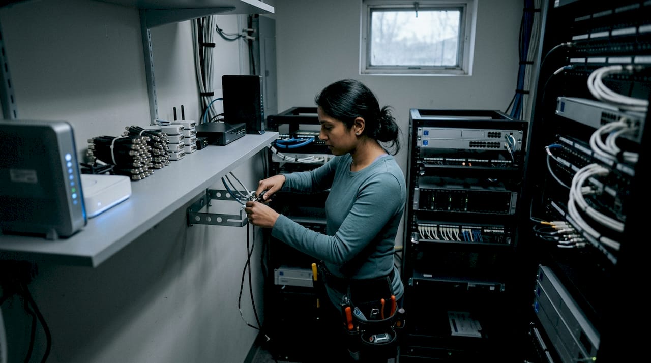
Typical DSL attenuation ranges from 5 dB to 50 dB depending on line length and cable quality. That range illustrates how dramatically signal strength can vary across real installations. A 50 dB loss on a DSL line means the signal at the far end is 100,000 times weaker than at the source.
The industry standard unit for measuring signal degradation is the decibel (dB). Engineers use it because signal loss compounds logarithmically, not linearly. Adding losses in dB is as simple as adding numbers, which makes system design far more practical.
What causes signal attenuation in wired and wireless systems?
The primary causes of attenuation are distance, material absorption, scattering, and frequency. Each one acts differently depending on the medium, and most real-world signal problems involve more than one cause at once.
Distance and spreading loss
As a signal radiates outward, its energy spreads across a larger area. This is called spreading loss or free-space path loss. The path loss exponent describes how fast this spreading happens. In free space, the exponent is 2. In a complex indoor environment with walls, furniture, and interference, the path loss exponent can reach 6. That means signal strength drops far faster indoors than most people expect.
Material absorption and frequency dependence
Different materials absorb signal energy at different rates. Concrete, metal, and water are the worst offenders for wireless signals. In copper cables, higher frequencies attenuate faster due to the skin effect, where current concentrates near the wire’s surface and increases resistance. This is why Cat5e cable works fine for older networks but Cat6a is required for modern high-speed applications.
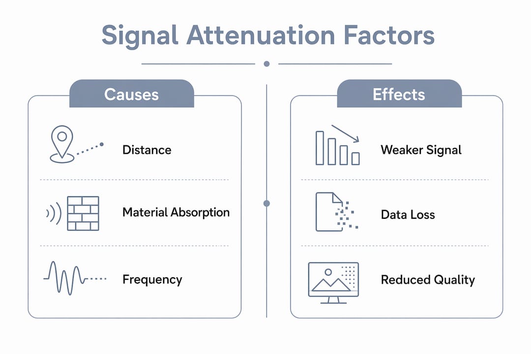
Atmospheric absorption is a major factor for wireless systems at high frequencies. Significant absorption peaks occur at 22 GHz, 60 GHz, and 183 GHz. The 60 GHz band, used in some Wi-Fi 6E and millimeter-wave applications, loses signal so fast in air that it is only practical over very short distances.
Fiber optic bending and physical damage
Fiber optic cables are not immune to attenuation. Macro-bending in fiber optics causes abrupt signal loss that is often mistaken for distance-related degradation. A cable bent too tightly around a corner can lose as much signal as several hundred feet of straight cable. This is one of the most common and most overlooked causes of fiber performance problems.
- Distance: longer runs always mean more loss, regardless of medium
- Frequency: higher frequencies lose energy faster in both copper and wireless
- Material: concrete, metal, and water block or absorb wireless signals
- Physical damage: kinks, tight bends, and crushed cables add significant loss
- Connectors: every poorly terminated connector adds measurable loss to the path
- Temperature extremes can make cables brittle and degrade their signal-carrying properties over time
Pro Tip: When troubleshooting a weak signal, check the physical cable run before replacing any hardware. A single tight bend or a connector crimped at the wrong angle can cause more loss than 200 feet of cable.
How is signal attenuation measured?
Attenuation is expressed in decibels (dB) using a logarithmic scale. The formula for power attenuation is:
Attenuation (dB) = 10 × log₁₀(P_out / P_in)
For voltage measurements, the formula changes slightly:
Attenuation (dB) = 20 × log₁₀(V_out / V_in)
The logarithmic scale is not arbitrary. It matches how human perception works and how signal loss actually compounds. Adding two 3 dB losses gives 6 dB total loss, which equals 75% power loss. The math stays clean and additive, which is why engineers rely on it.
Common attenuation reference values
| Loss (dB) | Power Remaining | Practical Meaning |
|---|---|---|
| 3 dB | 50% | Signal half as strong |
| 10 dB | 10% | Signal ten times weaker |
| 20 dB | 1% | Significant degradation |
| 30 dB | 0.1% | Near unusable without amplification |
How professionals measure attenuation in the field
- Optical Time Domain Reflectometer (OTDR): Used for fiber optic cables. An OTDR sends a light pulse into the fiber and measures reflections to locate faults, splices, and loss points along the entire run.
- Cable certifiers: Used for copper cabling. These devices send test signals across a cable and report pass or fail results against standards like TIA-568 or ISO/IEC 11801.
- Signal level meters: Used for coaxial and RF systems. These measure received signal strength in dBm or dBmV at the end of a cable run.
- Spectrum analyzers: Used for wireless systems. They display signal strength across a frequency range and help identify interference and dead zones.
Attenuation accumulates across every cable, connector, and component in a signal path. The weakest link determines the system’s overall performance. This is why measuring the full path, not just one segment, gives the only accurate picture.
What effects does signal weakening have on system performance?
Signal weakening reduces the signal-to-noise ratio (SNR). When the signal drops but background noise stays constant, the receiving device has a harder time separating the real signal from interference. Below a certain SNR threshold, the system fails entirely.
The effects look different depending on the system:
- DSL and broadband: Slower speeds, higher error rates, and frequent disconnections on long copper runs
- Fiber optic networks: Reduced data throughput and increased bit error rates when loss exceeds the link budget
- Wireless networks: Dead zones, slow speeds, and dropped connections in areas far from the access point
- Security cameras: Blurry or pixelated video, dropped feeds, and recording gaps caused by weak signal on long cable runs
- Cell signals: Dropped calls, slow data, and failed text messages inside buildings with thick walls
Signal attenuation reduces amplitude without changing the waveform’s shape. Distortion, by contrast, alters the waveform itself and requires more complex correction. Attenuation is often correctable with amplification alone. Distortion is not. Knowing which problem you have determines which fix actually works.
Attenuation differs from distortion in a critical way. Amplifying a distorted signal just makes the distortion louder. Amplifying an attenuated signal restores it cleanly, provided the noise floor has not already corrupted the data. This distinction matters when diagnosing a system that is not performing as expected.
How can you reduce and manage signal attenuation?
Managing signal attenuation comes down to two approaches: reducing the loss before it happens, and compensating for it after it occurs. The best installations use both.
Passive methods: reduce loss at the source
Passive mitigation means making design and installation choices that minimize attenuation without adding powered equipment.
| Method | Application | Effect |
|---|---|---|
| Shorter cable runs | All wired systems | Less distance means less loss |
| Higher-quality cable | Copper networks | Cat6a reduces high-frequency loss vs. Cat5e |
| Proper fiber splicing | Fiber optic systems | Proper splicing adds only 0.05–0.3 dB per connection |
| Avoiding tight bends | Fiber optic cables | Prevents macro-bend loss |
| Quality connectors | All wired systems | Poorly terminated ends add measurable loss |
Choosing the right cable for the job is the single most cost-effective passive strategy. A fiber optic vs. copper cable comparison shows that fiber carries signals over far greater distances with far less loss, making it the right choice for long runs in any modern installation.
Active methods: compensate for unavoidable loss
Active mitigation adds powered devices to the signal path to restore strength.
Amplifiers boost signal strength at a specific point in the path. They work best when the signal is still clean enough to amplify without also amplifying noise. Repeaters go further by receiving, decoding, and retransmitting the signal, which eliminates accumulated noise entirely. Cell boosters capture a weak outdoor signal, amplify it, and rebroadcast it indoors. For South Florida properties with thick concrete construction, cell booster installation is often the most practical fix for persistent indoor dead zones.
Link budget calculations are the professional standard for planning any signal system. A link budget adds up every gain and every loss across the full signal path before installation begins. Link budget calculations prevent the common mistake of discovering a system does not work after everything is already installed and terminated.
Pro Tip: Always run a link budget before purchasing equipment. Add up cable loss, connector loss, and any passive splitter loss. Then confirm your amplifier or booster gain exceeds the total loss by at least 10 dB to maintain a reliable margin.
Key Takeaways
Signal attenuation is a predictable, measurable loss that every communication system faces, and it is manageable with the right design choices and equipment.
| Point | Details |
|---|---|
| Attenuation is measured in dB | A 3 dB loss equals 50% power loss; a 10 dB loss means the signal is ten times weaker. |
| Distance and frequency drive loss | Higher frequencies and longer runs always produce more attenuation in any medium. |
| Every component adds loss | Cables, connectors, and splices all contribute; the weakest link limits the whole system. |
| Passive fixes come first | Shorter runs, quality cable, and proper termination reduce loss before active equipment is needed. |
| Link budgets prevent surprises | Calculate total path loss before installation to confirm the system will perform as designed. |
What I’ve learned from years of diagnosing signal problems
The most common mistake I see is treating signal problems as equipment failures when the real cause is installation quality. A technician replaces a camera, a router, or a booster, and the problem comes right back because the cable behind the wall has a tight bend or a connector that was never properly terminated.
Network reliability is often compromised by installation errors more than by the inherent limits of the equipment. That finding matches exactly what I see in the field. The cable run matters more than the device at the end of it.
The other thing professionals underestimate is frequency dependence. A cable that tests fine at 100 MHz can fail badly at 500 MHz. When a client upgrades to a faster network standard, the existing cabling sometimes cannot support it, not because it is damaged, but because it was never rated for those frequencies. Attenuation accumulates across every component, so a marginal cable plus a marginal connector plus a long run can push a system past its limit even when each individual piece looks acceptable.
My advice: assess the full signal path as a system, not as a collection of separate parts. Measure from source to destination. Check every connector. Confirm every bend radius. That approach finds problems that component-by-component testing misses entirely.
— Aaron
Signal problems Lowvoltagecorp can solve for you
Weak signals cost real money. Dropped camera feeds miss critical events. Dead cell zones frustrate tenants and staff. Slow networks reduce productivity. Lowvoltagecorp specializes in diagnosing and fixing exactly these problems across security cameras, wired and wireless networks, and cell booster systems.

The team at Lowvoltagecorp handles the full signal path: cable selection, proper termination, booster placement, and link budget verification before any equipment goes in. For South Florida property managers and homeowners, the signal boosting guide covers the most common attenuation problems in the region’s concrete-heavy construction. For security system performance, the surveillance lighting and signal guide connects signal quality directly to camera reliability. Contact Lowvoltagecorp for a professional site assessment before your next installation or upgrade.
FAQ
What is signal attenuation in simple terms?
Signal attenuation is the loss of signal strength as it travels through a cable or through the air. The longer the distance or the higher the frequency, the more strength the signal loses.
How is attenuation different from distortion?
Attenuation reduces signal amplitude without changing its shape, so amplification can restore it. Distortion alters the waveform itself and requires more complex correction than simple amplification.
What unit measures signal attenuation?
Attenuation is measured in decibels (dB). A 3 dB loss equals 50% power loss, and a 10 dB loss means the signal is ten times weaker than the original.
What causes the most signal loss in a building?
Concrete walls, metal structures, long cable runs, and poorly terminated connectors are the leading causes of signal loss inside buildings. Tight bends in fiber optic cables also cause significant, often overlooked loss.
Can signal attenuation be fixed without replacing cables?
Yes. Amplifiers, repeaters, and cell boosters can compensate for attenuation on existing cable runs. However, cables with physical damage or improper termination should be repaired or replaced for a lasting fix.