A gate system is UL 325 compliant when the operator carries a valid UL 325 listing, every entrapment zone is protected by two independent means of entrapment protection, the gate structure meets ASTM F2200 guarding and screening requirements, all controls are mounted at least 6 feet from moving parts, required warning signs are posted, and external entrapment devices are monitored by the operator at least once per open/close cycle. That is the non-negotiable floor. Your immediate next step: walk the gate site, map every entrapment zone, and pull the operator’s label to confirm its UL 325 listing and class rating.
Key requirements at a glance:
- Two independent means of entrapment protection per entrapment zone (inherent sensing counts as one if listed by the manufacturer)
- Operator listed to UL 325 and permanently labeled with class, maximum gate size, and weight
- Gate construction compliant with ASTM F2200 guarding, screening, and sphere-test requirements
- Controls located a minimum of 6 feet from any moving gate component
- Warning signs posted at the gate and at each control location
- Monitoring of external entrapment devices confirmed each operating cycle
Key Takeaways
UL 325 gate compliance requires a listed operator, two independent means of entrapment protection per zone, ASTM F2200-compliant gate screening, controls at least 6 feet from moving parts, and documented cycle-by-cycle monitoring of all external devices.
| Point | Details |
|---|---|
| Two means per entrapment zone | Every identified entrapment zone needs two independent protection means; inherent sensing counts as one. |
| Operator listing is mandatory | The operator must carry a current UL 325 listing matched to the gate’s class, weight, and size. |
| ASTM F2200 screening required | Gate infill openings must pass the 2-1/4" sphere test below 6 feet; screening must attach to the gate, not a fixed post. |
| Controls 6 feet from moving parts | All control stations must be located at least 6 feet from any moving gate component. |
| Repairs can trigger upgrades | Significant modifications remove grandfathering; affected components must meet the current Seventh Edition of UL 325. |
| Lowvoltagecorp | Provides full UL 325 compliance site visits in South Florida, including testing, documentation, and AHJ-ready packets. |
Table of Contents
- How UL 325 is enforced across U.S. jurisdictions
- UL 325 vs. ASTM F2200: why you need both standards to pass
- What entrapment protection actually requires on site
- Guarding, screening, and the sphere tests that trip up inspections
- Operator classes and what the label must tell you
- Installation and inspection checklist for UL 325 compliance
- What inspectors and AHJs expect for testing and documentation
- Permits, inspection workflow, and preparing for the inspector
- How to bring a non-compliant gate into compliance
- The part of UL 325 compliance that most installers underestimate
- Lowvoltagecorp handles inspection-ready gate compliance in South Florida
- Sources
How UL 325 is enforced across U.S. jurisdictions
UL 325 is technically a voluntary consensus standard, but that label understates its real-world force. State and local jurisdictions adopt the International Building Code (IBC), International Fire Code (IFC), and International Residential Code (IRC), all of which reference UL 325 by name. Once adopted, building and fire inspectors enforce UL 325 clauses during property inspections as a matter of local law, not suggestion.
What that means practically: a gate operator that is not listed to UL 325 can trigger a stop-work order, a failed inspection, or a requirement to remove and replace the equipment before occupancy is granted. For property managers, the liability exposure goes further. If a person is injured by a non-compliant gate and the record shows the system was never brought to current standards, the property owner and the installing contractor both carry exposure.
Some states have gone further than the model codes. Nevada, for example, has statutes that specifically address automated gate safety and reference UL 325 operator requirements by name. Even in jurisdictions without explicit statutes, inspectors routinely check for the UL listing label, device placement, and signage as part of a standard permit inspection.
Pro Tip: Before pulling a permit for any gate motorization project, call the local Authority Having Jurisdiction (AHJ) and ask specifically whether they enforce UL 325 under the adopted IBC/IFC edition. Get the answer in writing. That one call can prevent a failed inspection.
Repairs matter here too. DASMA’s technical guidance is clear: significant repairs or modifications do not carry automatic grandfathering. A major alteration to the operator or safety peripherals typically triggers a requirement to bring those components up to the current edition of UL 325, which is the Seventh Edition, revised February 21, 2023, per the CPSC memorandum documenting the 2019 and 2023 revisions.
UL 325 vs. ASTM F2200: why you need both standards to pass
The single most common misconception in the field is that a UL-listed operator equals a compliant gate system. It does not. UL Solutions is explicit: UL 325 governs the electrical operator and its control systems, including entrapment-device monitoring requirements. ASTM F2200 governs the physical gate itself, covering construction, guarding, screening, and geometry. A UL-listed operator installed on a gate that fails ASTM F2200 screening requirements is still a non-compliant system.
| Requirement | Governing standard | What it covers |
|---|---|---|
| Operator listing and labeling | UL 325 | Electrical operator, controls, monitoring logic |
| Entrapment device types and monitoring | UL 325 | Photoeyes, contact edges, force sensing, cycle monitoring |
| Gate construction and geometry | ASTM F2200 | Frame, infill, structural integrity |
| Guarding and screening | ASTM F2200 | Openings, sphere tests, screening material |
| Sphere-test pass/fail criteria | ASTM F2200 | 2-1/4" and 4" sphere rules by gate type |
DASMA, the Door and Access Systems Manufacturers Association, publishes technical guidance that bridges both standards and is widely used by inspectors and installers as a practical reference. The ICC model codes (IBC/IFC) reference both UL 325 and ASTM F2200, so an inspector working under an adopted IBC edition will check both.
Practical checklist for scope clarity:
- Use UL 325 to verify: operator listing, operator class, entrapment device compatibility, monitoring function, control-location requirements, and signage
- Use ASTM F2200 to verify: gate infill openings, guarding/screening material, sphere-test compliance, and gate geometry by type
- Use DASMA TDS #356 as a field-reference FAQ that interprets both standards for common installer questions
What entrapment protection actually requires on site
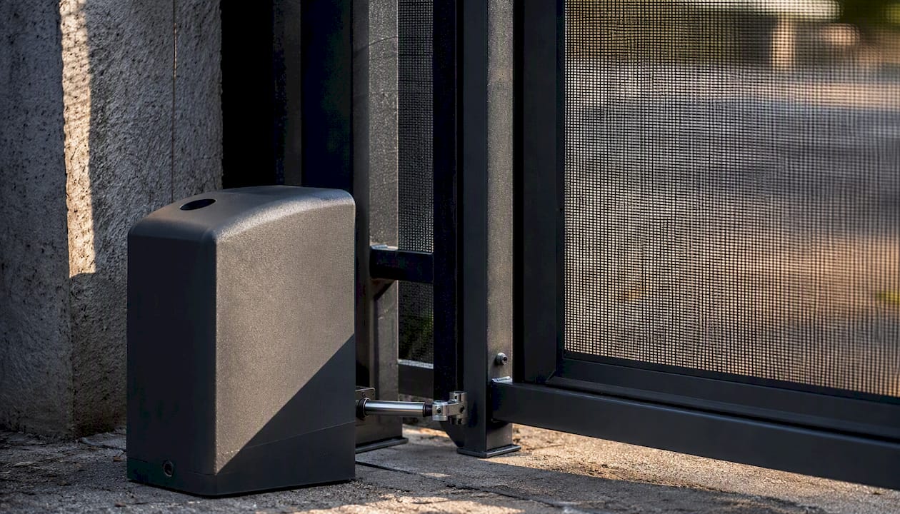
An entrapment zone is any area where a person or body part could be caught, crushed, or sheared by a moving gate or its components. The specific zones vary by gate type. A horizontal sliding gate creates entrapment zones at the leading edge, the trailing edge, the area between the gate and a post or wall, and the gate’s drive mechanism. Swing gates create zones at the pivot point and along the arc of travel. Vertical lift and pivot gates create overhead and underside zones.
DASMA’s guidance and UL 325 itself require two independent means of entrapment protection for each identified entrapment zone. Inherent force-limiting sensing built into the operator counts as one means, provided the manufacturer lists it for that purpose. The second means must be an external device. For swing gates, inherent sensing alone may satisfy the requirement in some configurations, but that exception is narrow and manufacturer-specific.
Acceptable device categories per UL’s guidance on external entrapment protection devices:
- Non-contact photoelectric sensors (photoeyes/photobeams): detect an obstruction in the gate’s path without physical contact; must be listed and placed to cover the entrapment zone
- Contact/pressure-sensing edges: mounted on the leading or trailing edge of the gate; trigger reversal on physical contact with an obstruction
- Monitored external devices: any external device the operator actively monitors for presence and electrical continuity at least once per open/close cycle
- Constant-pressure controls: require continuous operator input to move the gate; the gate stops when the button is released; typically used in commercial applications where an operator is present
- Inherent force-limiting sensing: built-in motor current or torque monitoring that reverses the gate when resistance exceeds a threshold; counts as one means only when listed by the manufacturer for that gate class
Pro Tip: Never rely on a single photoeye beam to cover two physically separate entrapment zones. Each zone needs its own independent means. A beam that crosses one zone does not satisfy the requirement for an adjacent zone, even if the beam physically passes near it.
Understanding the sensor terminology for each device type helps property managers verify that the right equipment is installed before an inspector arrives.
Guarding, screening, and the sphere tests that trip up inspections
ASTM F2200 sets the physical requirements for gate openings, and the sphere tests are the most commonly failed items during inspections. The rule is straightforward in principle: openings in a gate’s infill must not allow a sphere of a specified diameter to pass through, because that diameter approximates a child’s head or neck.
- 2-1/4-inch sphere test: applies to the bottom portion of horizontal sliding gates and vertical pivot gates, from the bottom of the gate up to 6 feet above grade. Any opening that passes a 2-1/4-inch sphere in that zone fails.
- 4-inch sphere test: applies to the upper portion of the gate above 6 feet, and to some gate types where the lower zone is already guarded by a solid barrier.
For horizontal sliding gates, screening must cover the bottom of the gate to a height of 6 feet above grade, or to the full height of the gate if the gate is shorter than 6 feet. The screening material must be attached to the gate itself, not to a fixed structure, so that it moves with the gate and cannot create a shear point.
Common inspection failures and their fixes:
- Open picket spacing below 6 feet on a sliding gate: add screening material (welded wire mesh or solid panel) to bring openings below the 2-1/4-inch threshold
- Decorative infill with large openings: measure every opening with a physical sphere gauge before the inspector arrives; replace or add screening where needed
- Screening attached to a fixed post instead of the gate: re-attach to the gate frame so it travels with the gate
- No guarding on the drive mechanism: install a physical guard over the rack, chain, or drive assembly to prevent entrapment at the drive
A 2-1/4-inch sphere gauge costs very little and takes minutes to use. Running it across every gate panel before calling for inspection is one of the fastest ways to avoid a re-inspection fee.
Operator classes and what the label must tell you
UL 325 defines operator classes by the type of installation environment and the gate’s intended use. The class system exists because a residential driveway gate and a high-traffic commercial parking gate face different duty cycles, speeds, and user populations.
- Class I: residential vehicular gate; single-family home or estate; low traffic
- Class II: commercial or general-access vehicular gate; multi-family residential or mixed-use; higher traffic
- Class III: industrial vehicular gate; limited access; typically monitored by a trained operator
- Class IV: restricted-access vehicular gate; highest security; operator present at all times
The operator’s permanent label must state the class or classes it is listed for, the maximum gate weight it is rated to move, and the maximum gate size. Matching the operator to the gate is not optional. An operator rated for a Class I residential gate installed on a high-traffic Class II commercial property is non-compliant regardless of how well it functions mechanically.
During a site acceptance test, pull the operator’s label and compare it against:
- The gate’s measured weight (weigh it or obtain the fabricator’s spec sheet)
- The gate’s width and height
- The property’s use classification (residential, commercial, industrial, restricted)
- The manufacturer’s installation instructions for compatible external entrapment devices
If the operator label does not match the gate specs or the property class, the operator must be replaced before the system can pass inspection.
Installation and inspection checklist for UL 325 compliance
Use this checklist during installation, at handoff, and before any inspector visit. For a full motorized gate installation walkthrough, the steps below map to the compliance-critical items inspectors focus on.
Pre-installation checks:
- Confirm the operator carries a current UL 325 listing (check the UL Product iQ database or the operator’s label)
- Verify the operator class matches the gate’s use classification
- Confirm the operator’s rated weight and size capacity exceeds the gate’s actual weight and size
- Obtain the manufacturer’s list of compatible external entrapment devices
- Review ASTM F2200 requirements for the specific gate type being installed
Device placement and wiring:
- Identify every entrapment zone for the gate type (leading edge, trailing edge, pivot/hinge area, drive mechanism)
- Assign two independent means of protection to each zone; document the device type and location for each
- Confirm all external devices appear on the operator manufacturer’s approved compatibility list
- Wire all external devices per the manufacturer’s wiring diagram; verify monitoring connections are active
- Confirm the operator’s monitoring function is enabled and will check device continuity each cycle
On-site testing:
- Run the gate through a minimum of five complete open/close cycles; verify monitoring triggers on each cycle
- Test the force-limiting/inherent sensing by placing a 1-inch-diameter rigid cylinder on the ground in the gate’s path; confirm reversal
- Disconnect one external device and attempt to cycle the gate; confirm the operator halts or alerts as required
- Measure all control locations; confirm each is at least 6 feet from any moving gate component
- Verify all required warning signs are posted at the gate and at each control station
Documentation and signage:
- Photograph the operator label, each entrapment device and its placement, all control locations, and all signage
- Complete a test log recording cycle counts, force-test results, and monitoring-check results
- Compile the operator manual, device compatibility list, test log, and photos into a documentation packet for the AHJ
What inspectors and AHJs expect for testing and documentation
“Listed to UL 325” means the operator was tested by a nationally recognized testing laboratory (NRTL) and found to meet the standard’s requirements. The listing is tied to the specific model; a label on one unit does not cover a different model from the same manufacturer. Inspectors verify the listing by checking the label on the unit itself and, increasingly, by looking up the model in the UL Product iQ database on-site.
Documentation inspectors typically request:
- Operator label: must be permanently affixed, legible, and state the UL 325 listing, class, and gate size/weight limits
- Operator installation manual: confirms compatible devices, wiring diagrams, and the manufacturer’s installation requirements
- Device compatibility list: shows which external entrapment devices the manufacturer has approved for use with that operator model
- Test log: records sensitivity tests, monitoring-check results, and cycle counts from the installation date forward
- Photos: before and after installation, showing device placement, control locations, and signage
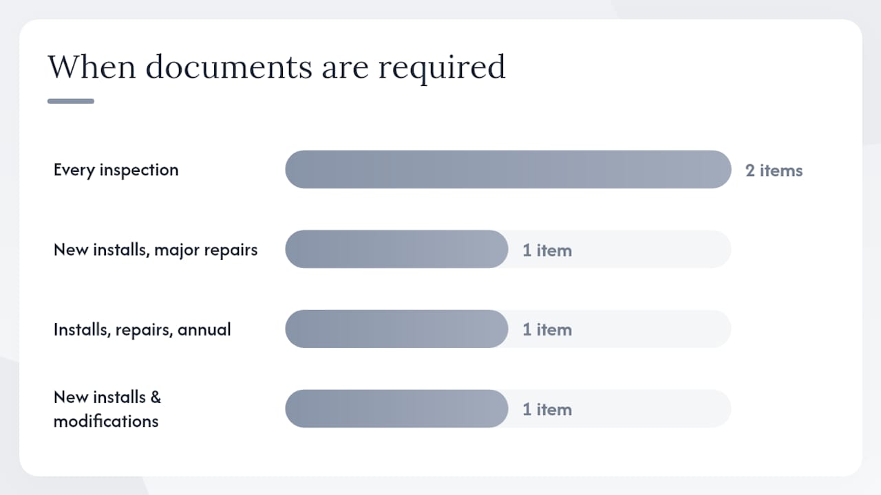
The repair trigger is the most overlooked documentation issue. DASMA’s FAQ is direct: significant repairs or modifications do not carry automatic grandfathering. If a contractor replaces the operator, rewires the control system, or makes structural changes to the gate, the affected components must meet the current Seventh Edition of UL 325. Older operators manufactured before roughly 2000 often lack the input terminals and monitoring logic needed to accept modern entrapment devices, making them effectively non-upgradeable. Replacement is the only compliant path.
| Documentation item | Purpose | When required |
|---|---|---|
| Operator label (photo) | Confirms listing, class, and gate specs | Every inspection |
| Installation manual | Verifies compatible devices and wiring | New installs and major repairs |
| Device compatibility list | Proves external devices are approved | Every inspection |
| Test log | Demonstrates monitoring and force tests | New installs, repairs, annual maintenance |
| Before/after photos | Documents placement and signage | New installs and modifications |
Permits, inspection workflow, and preparing for the inspector
Most jurisdictions require a permit when motorizing a gate, adding or replacing an operator, or making significant changes to an existing automated gate system. The permit threshold varies by AHJ. Some require a permit for any electrical work on a gate; others set a dollar threshold. The only reliable way to know is to call the local building department before starting work.
What inspectors check during a gate permit inspection:
- UL 325 listing label on the operator (model number, class, and gate specs must be legible)
- Entrapment device placement relative to each identified entrapment zone
- Evidence of two independent means per zone (device type, location, and wiring)
- Control location measurements (6-foot minimum from moving parts)
- Warning sign placement and content
- ASTM F2200 screening and sphere-test compliance on the gate structure
- Monitoring function verification (inspector may ask for a live cycle demonstration)
Prepare a documentation packet before the inspection date. Include the operator manual, the device compatibility list, the test log from installation, and photographs of every compliance item. Inspectors who receive a complete packet at the start of an inspection move faster and flag fewer items for re-inspection.
For code questions that go beyond the local AHJ’s expertise, the escalation path is: UL Solutions (for operator listing questions), the ICC (for code-adoption questions), and DASMA (for gate-specific technical interpretation). All three publish contact information and technical resources on their websites.
How to bring a non-compliant gate into compliance
When an inspector flags a gate, the remediation is rarely just swapping a sensor. DASMA’s guidance and field experience both confirm that corrections typically involve both electrical and mechanical work.
Step 1: Triage the violations
- List every flagged item from the inspection report; group by category: operator listing, entrapment protection, guarding/screening, control locations, signage
- Identify any immediate safety hazards (gate moving without any entrapment protection); post a manual-operation notice and disable automatic operation until corrected
- Determine whether the existing operator can accept the required external devices; check the manufacturer’s compatibility list
Step 2: Remediate in priority order
- If the operator is unlisted or incompatible with required devices, replace it with a UL 325-listed model rated for the gate’s class, weight, and size; see modern gate automation options for current hardware
- Procure external entrapment devices from the operator manufacturer’s approved list; never mix devices from an unapproved list
- Install and wire devices per the manufacturer’s diagram; confirm monitoring connections
- Re-screen or re-guard the gate structure to meet ASTM F2200 sphere-test requirements; attach screening to the gate frame, not to fixed posts
- Relocate any controls found within 6 feet of moving parts; run new conduit if needed
Step 3: Test and document
- Run the full on-site test sequence from the installation checklist above (steps 11–15)
- Complete a new test log with the remediation date, all test results, and the technician’s name
- Photograph every corrected item: new device placement, updated screening, relocated controls, new signage
- Compile the updated documentation packet and submit to the AHJ for re-inspection sign-off
Pro Tip: The most common retrofit trap is an older operator that has no terminal block or input provision for external entrapment devices. If the operator’s wiring diagram shows no monitored-device input, no amount of external sensors will make it compliant. Budget for operator replacement from the start of any remediation project, not as a last resort.
The part of UL 325 compliance that most installers underestimate
The standard does not tell you where to put the sensors. That is the installer’s responsibility, and it is where most compliance failures originate. UL 325 defines what a compliant device must do and how the operator must monitor it. ASTM F2200 defines what the gate structure must look like. Neither standard draws a map of your specific site.
That gap is intentional. Every gate installation is different: the geometry, the traffic pattern, the adjacent structures, and the use class all affect where entrapment zones exist and which device types can physically cover them. An installer who treats the standard as a shopping list (“two photoeyes, done”) without first mapping the zones is not compliant, even if the devices themselves are listed and monitored.
The UL 325 external entrapment protection device guidance makes the installer’s responsibility explicit: placing a compliant device in the wrong location renders the installation non-compliant. A photoeye mounted to cover the leading edge does nothing for the entrapment zone at the trailing edge or the drive mechanism. Both zones need their own independent means.
Documented testing is the proof. An inspector cannot see whether the monitoring function ran correctly on cycle 47 six months ago. A test log can. Installers who maintain cycle logs from day one give property managers a defensible record and give themselves protection if a claim ever arises. That log is not extra work; it is the difference between a clean re-inspection and a protracted dispute.
Lowvoltagecorp handles inspection-ready gate compliance in South Florida
Gate compliance work that passes inspection the first time requires more than installing the right hardware. It requires a documented site survey, correctly placed and monitored entrapment devices, ASTM F2200-verified screening, and a complete documentation packet ready for the AHJ before the inspector arrives.

Lowvoltagecorp provides the full compliance workflow for property and facility managers in South Florida: site survey and entrapment-zone mapping, procurement and installation of UL 325-listed operators and compatible external devices, on-site sensitivity and monitoring tests, ASTM F2200 screening verification, and a complete documentation packet including test logs, photos, and labeling verification. A typical compliance site visit produces a ready-to-submit packet the same day. For properties with existing gates that need remediation, the motorized gate installation and compliance service covers the full scope from triage to inspector sign-off. Contact Lowvoltagecorp to schedule a compliance site visit.
Sources
These are the primary documents to consult and attach to permit submittals:
- UL 325 and Gate Installations: Frequently Asked Questions (Note: References to UL 325 have been updated to the 7 th Edition)
- Residential Garage Door Operators — Revision of UL Standards Engagement (CPSC memorandum)
- Securing Peace of Mind: Access Control and Gate Operators | UL Solutions
- UL 325 | UL Standards & Engagement | UL Standard
This article is general information, not a substitute for advice from a qualified lawyer. Consult a qualified legal professional about your own circumstances before acting on anything here.