Gate sensor terminology is the specialized vocabulary that describes the sensor technologies, components, and functions used to monitor and control automated gates for safety and access control. Property and facility managers who understand these definitions communicate more clearly with technicians, catch system errors earlier, and stay compliant with standards like UL 325. The core sensor categories you need to know are photoelectric sensors (also called photo-eyes), safety edges, and loop detectors. Lowvoltagecorp works with all three types during gate installation, repair, and maintenance across residential and commercial properties.
What are the main types of gate sensors and their definitions?
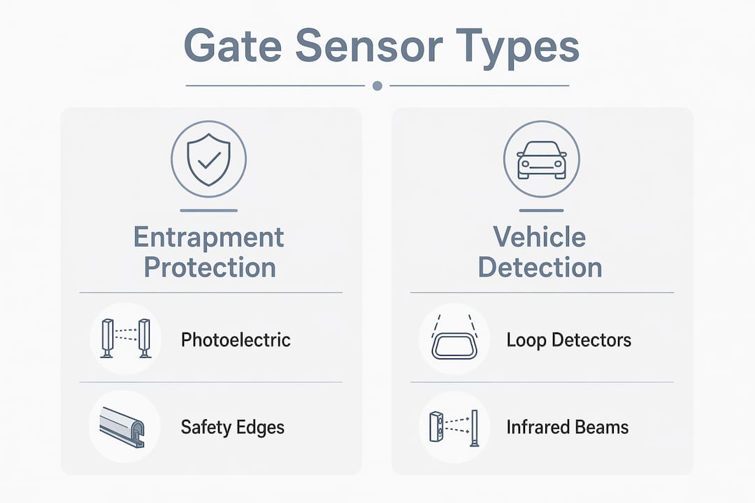
Gate sensors fall into two broad functional groups: entrapment protection devices and vehicle detection devices. Knowing which group a sensor belongs to tells you immediately what it does and what standard governs it.
Photoelectric sensors (photo-eyes)
Photo-eye sensor pairs emit and receive low-voltage infrared beams across the gate opening. When an obstacle breaks the beam, the receiver sends a signal to the gate controller to stop or reverse movement. This beam-break detection method is the most common form of obstacle sensing in automated gate systems. The term “photo-eye” refers to the paired emitter and receiver units working together as a single detection unit.
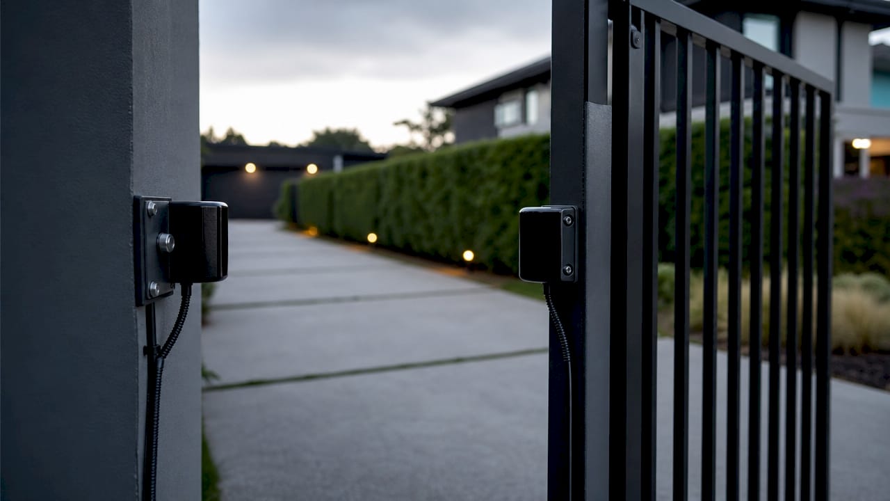
Safety edges
Safety edges detect pressure at the gate’s leading or trailing edge through resistive, pneumatic, or mechanical mechanisms. Contact with an obstacle compresses the edge, changes the sensor’s electrical state, and triggers a stop or reverse command. Resistive safety edges use a conductive rubber strip that closes a circuit under pressure. Pneumatic edges use air pressure changes inside a sealed tube. Mechanical edges use physical switches activated by compression.
Loop detectors
Inductive loop detectors are electromagnetic sensors embedded in the driveway surface to detect the metal mass of a vehicle. When a vehicle passes over the loop, the change in inductance signals the gate controller to open or hold the gate open. Loop detectors are vehicle detection devices, not entrapment protection devices. UL 325 recognizes this distinction, and property managers should too.
Infrared sensors and safety beams
Infrared sensors and safety beams are often used interchangeably with photo-eyes in field conversation, but they are not identical. A safety beam is a specific application of infrared technology placed at a defined height to detect pedestrians or vehicles in the gate path. Knowing the difference prevents miscommunication when ordering replacement parts or requesting service.
Pro Tip: When a technician references a “photo-eye,” confirm whether they mean a standalone infrared beam or a full transmitter-receiver pair. The distinction affects alignment procedures and replacement part numbers.
How do gate sensors work together to ensure safety and access control?
No single sensor type covers every safety scenario. Effective gate systems combine multiple sensor types to create layered protection.
Sensor input signals change state when an obstacle is detected, and the gate controller reads those state changes to trigger stop or reverse commands on the motorized operator. The controller is the central brain. Each sensor feeds it a binary signal: clear or obstructed. The controller’s response depends on which input tripped and during which phase of gate movement.
A standard installation for a commercial sliding gate typically follows this layered approach:
- Photoelectric beams are mounted at the gate opening to detect pedestrians and objects in the path of travel during closing.
- Safety edges are attached to the leading edge of the gate to detect contact with any obstacle the beam missed, particularly low objects or animals.
- Loop detectors are embedded in the driveway on both the entry and exit sides to detect vehicle presence and prevent the gate from closing on a vehicle.
- Secondary photo-eyes are sometimes added at vehicle height on the opposite side of the gate to create cross-beam coverage for larger openings.
UL 325 mandates specific entrapment protection devices for automatic gate operators and categorizes operators by intended use into Class I through Class IV. Class I covers residential single-family use. Class IV covers industrial or limited-access commercial use. Each class has defined requirements for the number and type of entrapment protection devices. A facility manager overseeing a Class II or Class III installation needs to verify that the sensor array meets the correct class requirements, not just any UL 325 compliant setup.
Entrapment protection devices (photo-eyes, safety edges) and vehicle detection devices (loop detectors) serve different safety functions and are governed by separate requirements under UL 325. Mixing up these categories during a service call can lead to a non-compliant installation.
Pro Tip: Ask your technician to label each sensor input on the controller diagram as either “entrapment protection” or “vehicle detection.” That one step makes future troubleshooting and compliance audits significantly faster.
What environmental conditions affect gate sensor performance?
Environmental conditions are the leading cause of sensor false triggers and system lockouts in outdoor gate installations. Understanding how weather interacts with each sensor type helps you choose the right equipment and set realistic maintenance schedules.
Heavy rain, fog, and direct sunlight can interfere with infrared signals in photoelectric sensors, causing false detections or signal loss. This is a critical reliability issue for properties in humid or high-glare climates. A gate that false-triggers during a rainstorm creates both a security gap and a liability risk.
Key environmental factors to evaluate when selecting sensors:
- IP rating (Ingress Protection): The IP rating system defines how well a sensor resists dust and water. An IP65 rating means the sensor is dust-tight and protected against water jets. Outdoor gate sensors should carry at least IP65 for reliable year-round performance.
- UV resistance: Direct sunlight degrades plastic sensor housings and can shift infrared beam alignment over time. UV-resistant housings extend sensor life in sun-exposed installations.
- Temperature range: Sensors specified for a narrow temperature range will fail or drift in climates with extreme heat or cold. Always verify the operating temperature range against your local climate.
- Sunlight immunity: Some photoelectric sensors include optical filters or modulated beam technology to reject ambient infrared from sunlight. This feature is non-negotiable for south-facing gate installations.
Loop detectors are less prone to weather interference than photoelectric sensors because they operate underground. However, they require well-sealed conduits to prevent water infiltration that can degrade the loop wire and cause detection failures. Weather-rated, high-quality gate sensors reduce false alarms and minimize maintenance-related downtime. That reduction in downtime directly lowers your operating cost over the life of the system. For properties in challenging climates, Lowvoltagecorp recommends reviewing durable sensor selection options before finalizing any gate sensor specification.
What is the terminology for gate sensor installation and troubleshooting?
Installation and troubleshooting conversations with technicians use a specific vocabulary. Property managers who know these terms catch billing errors, verify work quality, and diagnose recurring problems without waiting for a service call.
Core installation terms:
- Transmitter: The active half of a photoelectric sensor pair that emits the infrared beam. Always powered and always sending.
- Receiver: The passive half that detects the beam from the transmitter. Its output signal changes state when the beam is broken.
- Beam alignment: The process of physically positioning transmitter and receiver so the emitted beam hits the receiver’s detection window. Misalignment is the most common cause of new-installation failures.
- Safety input: A dedicated terminal on the gate controller that accepts a signal from an entrapment protection device. When the safety input trips, the controller stops or reverses the gate regardless of any other command.
- Safety circuit: The wiring loop connecting all safety inputs. An open circuit in this loop puts the gate into a fault state and prevents operation.
- Safety zone: The physical area monitored by the sensor array. Proper safety zone coverage means no part of the gate’s travel path is unmonitored.
- Edge-attached sensor: A safety edge mounted directly to the gate’s leading or trailing edge, moving with the gate during operation.
- In-ground loop: A loop detector wire cut into the pavement and sealed with epoxy or loop sealant. The term distinguishes it from surface-mounted detection alternatives.
Common error states and their terminology:
- Fault state: The controller has detected an abnormal sensor signal and has disabled gate movement until the fault is cleared.
- False trigger: A sensor reports an obstacle when none is present. Common causes include misalignment, weather interference, or a failing sensor.
- Sensor lockout: The gate refuses to operate because a sensor input is permanently tripped. This often indicates a wiring fault or a failed sensor rather than an actual obstruction.
- LED indicator: Most sensors include one or more LEDs that show power status, beam status, and fault conditions. A solid green LED typically means the beam is clear. A flashing or red LED indicates a fault or beam break.
Pro Tip: Before calling for service on a sensor lockout, check the sensor LED first. A solid red on the receiver almost always means beam misalignment, not a failed sensor. Realigning the transmitter takes minutes and costs nothing.
For a full walkthrough of sensor-related fault codes and controller inputs, the gate troubleshooting guide from Lowvoltagecorp covers the most common scenarios property managers encounter.
Key Takeaways
Mastering gate sensor terminology is the single most effective step a property manager can take to improve safety compliance, reduce service costs, and communicate clearly with technicians.
| Point | Details |
|---|---|
| Know your sensor categories | Photoelectric sensors, safety edges, and loop detectors serve distinct functions under UL 325. |
| Understand UL 325 class requirements | Your gate’s operator class determines which entrapment protection devices are required by standard. |
| Match sensors to your environment | Select IP65-rated, UV-resistant, and sunlight-immune sensors for outdoor installations in harsh climates. |
| Learn installation terminology | Terms like transmitter, receiver, safety input, and fault state help you verify work quality and diagnose issues. |
| Use LED indicators first | Checking sensor LEDs before calling for service resolves many common fault states without a technician visit. |
Why terminology is the first thing I teach property managers
Property managers often assume that gate sensor knowledge belongs entirely to the technician. That assumption costs money. I have seen facilities pay for repeat service calls on problems that a manager could have diagnosed in two minutes by reading a sensor LED or checking a safety circuit connection.
The terminology gap also creates security risks that are harder to see. A manager who cannot distinguish between an entrapment protection device and a vehicle detection device cannot verify that a post-installation inspection actually confirms UL 325 compliance. They sign off on work they cannot evaluate. That is a liability waiting to surface.
Environmental knowledge is equally undervalued. A manager who understands IP ratings and sunlight immunity can write a sensor specification that eliminates false triggers before the system is even installed. That is a better outcome than troubleshooting a misspecified sensor for three years. Lowvoltagecorp’s approach to security equipment maintenance starts with making sure the right sensor is in the right location before any maintenance schedule is set.
The managers who get the most out of their gate systems are the ones who ask specific questions. Not “is the sensor working?” but “is the safety input showing a clear state on the controller?” That level of specificity changes the conversation with every technician who walks on site.
— Aaron
Gate sensor installation and maintenance support from Lowvoltagecorp
Lowvoltagecorp specializes in the installation, repair, and maintenance of motorized gates, including full sensor array setup for residential and commercial properties. Whether you are specifying sensors for a new installation or tracking down a recurring fault on an existing system, having the right technical support matters.
The motorized gate installation guide from Lowvoltagecorp walks property managers through sensor mounting positions, controller wiring, and compliance checkpoints for UL 325 class requirements. For properties looking to reduce energy costs alongside security upgrades, the energy-efficient security tips resource covers sensor selection strategies that lower both false trigger rates and power consumption. Contact Lowvoltagecorp directly for a site assessment tailored to your gate system and property type.
FAQ
What is gate sensor terminology?
Gate sensor terminology is the specialized vocabulary describing the sensor types, components, and functions used in automated gate systems. It includes terms like photo-eye, safety edge, loop detector, safety input, and UL 325 entrapment protection device.
What are the main types of gate sensors?
The three primary types are photoelectric sensors (photo-eyes), safety edges, and inductive loop detectors. Photo-eyes detect beam interruption, safety edges detect contact pressure, and loop detectors detect vehicle metal mass in the driveway.
What does UL 325 require for gate sensors?
UL 325 requires automatic gate operators to include entrapment protection devices such as photo-eyes and safety edges, with specific requirements varying by operator class (Class I through Class IV) based on the intended use of the gate.
How does weather affect gate sensor performance?
Heavy rain, fog, and direct sunlight can cause false triggers or signal loss in photoelectric and infrared sensors. Loop detectors are more weather-resistant but require sealed conduits to prevent water damage to the in-ground wiring.
What does a sensor fault state mean on a gate controller?
A fault state means the controller has detected an abnormal signal from a sensor input and has disabled gate movement. Common causes include beam misalignment, a wiring fault in the safety circuit, or a failed sensor unit.