Gate automation is the process of converting a manual gate into a fully automated, safe, and reliable entry system through precise installation, configuration, and testing. For property owners and managers, a properly automated gate delivers controlled access, reduced liability, and daily convenience without requiring someone to physically open and close it. Step by step gate automation covers every phase of the process: site assessment, mechanical mounting, electrical wiring, safety device integration, and final commissioning. Done correctly, the result is a system that operates a full open/close cycle in 10–20 seconds and holds up for years with minimal maintenance.
What do you need before starting gate automation?
Gate automation is not a simple plug-in product. Success requires accurate mechanical mounting, gate balance, and full commissioning before the system goes live. Skipping the preparation phase is the most common reason installations fail or create safety hazards.
Assess your gate type and site conditions
Your gate type determines everything about the motor and mounting hardware you need. Swing gates require a different motor mechanism than sliding gates, and the site terrain affects how you anchor the motor baseplate. Check for level ground, adequate clearance on both sides of the gate, and a stable post or pillar to mount the operator.
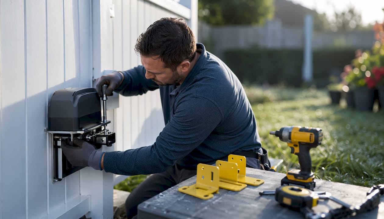
Power supply is the next decision. Mains power gives you consistent performance and supports heavier motors. Solar power suits remote locations but requires a correctly sized battery and panel to handle repeated daily cycles. Confirm which option your site supports before purchasing any equipment.
Tools and materials checklist
Gather these before you begin:
- Drill, masonry bits, and anchor bolts for baseplate mounting
- Spirit level and measuring tape for alignment
- Angle grinder with a metal cutting disc for gear rack trimming
- Screwdrivers, wire strippers, and a multimeter for electrical work
- Conduit and weatherproof cable for outdoor wiring runs
- Safety photocells, pressure edges, and warning signs
Pro Tip: Buy one extra meter of gear rack. Cutting to exact length on site is far easier than running short and ordering more.
Regulatory and safety requirements
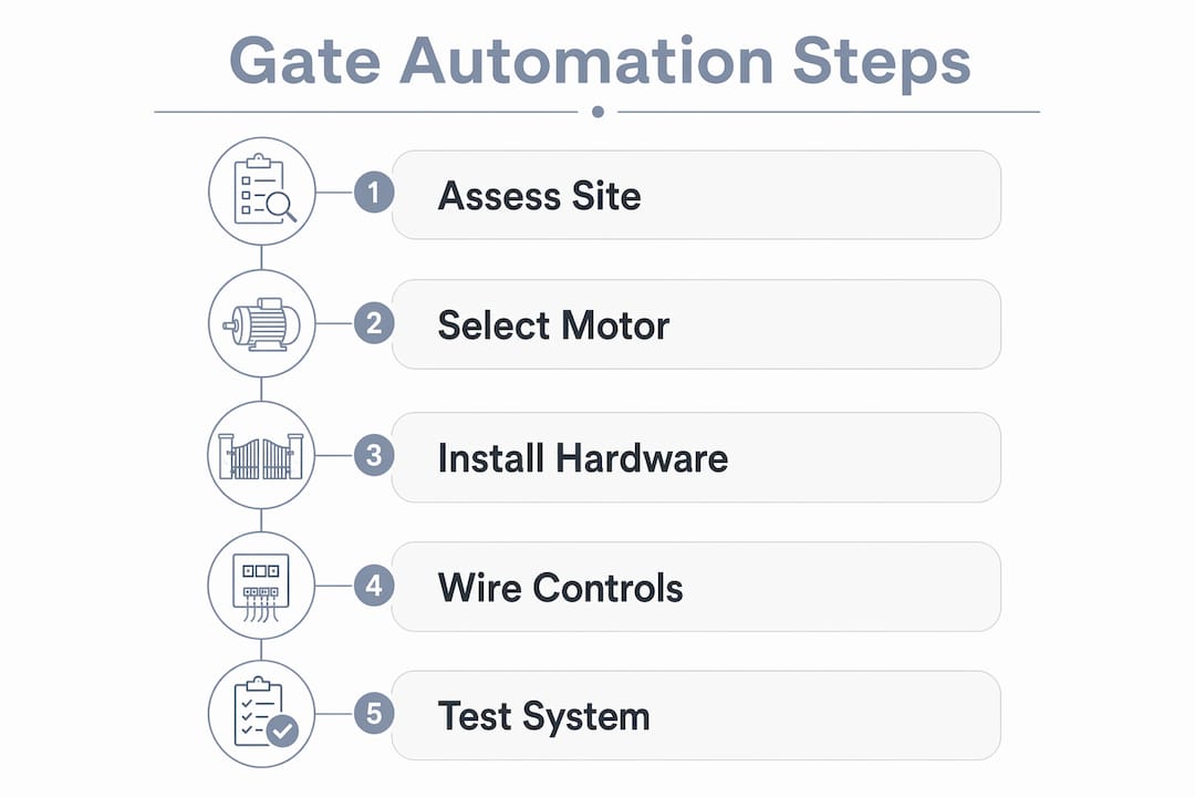
Gate automation is treated as machinery under safety regulations in many jurisdictions. A site-specific risk assessment and force testing to standards such as BS EN 12445 are required before the system goes into regular use. Even where local codes differ, documenting your risk assessment protects you legally and confirms the system is safe for everyone who uses the property.
| Requirement | Why it matters |
|---|---|
| Risk assessment | Identifies crush, shear, and entrapment hazards before installation |
| Force testing | Confirms the gate stops or reverses before injuring a person |
| Safety device verification | Proves photocells and pressure edges function correctly |
| Declaration of Conformity | Documents compliance for legal and insurance purposes |
How do you install the gate motor and gear rack?
Mechanical installation sets the foundation for everything else. Errors at this stage cause uneven gate movement, accelerated wear, and unreliable safety behavior. Follow these steps in order.
-
Position the motor baseplate. Place the baseplate against the gate post at the height specified in your motor’s installation manual. The motor pinion must align with the center of the gear rack you will install. Mark the anchor bolt positions with a marker.
-
Drill and anchor the baseplate. Use masonry bits sized for your anchor bolts. Drill to the required depth, insert the anchors, and torque the baseplate bolts to the manufacturer’s specification. A loose baseplate causes vibration and misalignment over time.
-
Install the gear rack. Lay the gear rack along the bottom of the gate, starting from the motor end. Clamp each section in place before drilling. The rack must sit level across its full length. Use a spirit level at every joint.
-
Set the backlash clearance. Slide the gate manually and check the gap between the motor pinion and the gear rack teeth. The correct backlash clearance is 2–3 mm. Too tight causes binding. Too loose causes skipping and inconsistent force readings during safety tests.
-
Test manual movement. Push the gate by hand through its full travel. It should move smoothly with no binding, scraping, or resistance spikes. Fix any friction points before connecting power.
-
Secure striker plates and trim the rack. Fix the open and close limit striker plates at the correct travel endpoints. Cut any excess gear rack flush with an angle grinder.
Pro Tip: Cover the motor with a cloth before cutting the gear rack. Metal sparks damage motor windings and void most manufacturer warranties.
How do you wire and configure the gate control system?
Electrical configuration turns a mounted motor into a functioning automated gate. Safety device configuration must integrate tightly with control programming because obstacle detection directly affects auto-close timing and reversal behavior.
Wiring the core components
Connect the motor leads to the control board terminals as labeled in your wiring diagram. Run a dedicated cable from your power supply to the control board, using conduit for any outdoor sections. Keep low-voltage signal cables separated from mains power cables to prevent interference.
Wire your trigger devices next. A keypad, remote receiver, or intercom connects to the trigger input terminals on the control board. Each device needs its own cable run back to the board. Daisy-chaining trigger devices is a common wiring mistake that causes intermittent operation.
Programming auto-close and remote controls
Most control boards support auto-close timers from 3 to 120 seconds. Set the timer based on your traffic flow. A residential driveway typically works well at 10–15 seconds. A commercial entrance with vehicle queuing may need 30–60 seconds. Program each remote control or keypad code according to the board’s pairing procedure and test every device before moving to safety wiring.
Integrating safety photocells and pressure edges
- Mount photocell transmitters and receivers at a height that catches pedestrians and vehicles, typically 300–500 mm above ground level.
- Run shielded cable from each photocell back to the designated safety input terminals on the control board.
- Wire pressure edges to the leading edge of the gate for contact detection during closing.
- Confirm the control board is set to reverse on photocell interruption during closing and to hold open during opening.
Safety photocells detect obstacles and prevent gate closure or reverse the gate if the beam is broken during a closing cycle. Each interruption also resets the auto-close timer, so test this interaction specifically during commissioning.
Pro Tip: When setting up a swing gate opener, temporarily disable safety inputs to confirm motor direction and travel limits first. Restore all safety inputs before running any commissioning tests.
How do you commission and test an automated gate?
Commissioning is the phase where you verify that every component works together correctly. Proper commissioning ensures compliance and safe operation before the gate enters regular use.
-
Run a manual open/close cycle. Use the control board’s manual trigger to open and close the gate. Confirm it reaches both limit positions cleanly and stops without impact.
-
Test each trigger device. Activate the gate from every remote, keypad, and intercom unit. Every device must trigger a clean cycle with no hesitation.
-
Verify photocell function. With the gate closing, break the photocell beam using a solid object. The gate must stop and reverse immediately. Repeat this test three times to confirm consistency.
-
Conduct force testing. Apply resistance to the gate during closing to simulate an obstruction. The gate must stop or reverse before the force exceeds the safe threshold defined in your local standard. Adjust the motor’s force setting if the gate pushes through without reversing.
-
Check auto-close timer behavior. Allow the gate to open and wait for the auto-close timer to trigger. Interrupt the photocell beam during the closing cycle and confirm the timer resets correctly.
-
Document your results. Record force test readings, photocell response times, and any adjustments made. This documentation supports your risk assessment and reduces liability if an incident occurs later.
Pro Tip: If force test results are inconsistent, recheck backlash clearance before adjusting motor force settings. Incorrect backlash causes uneven gate behavior that masks real safety function errors.
| Test | Pass condition | Common failure cause |
|---|---|---|
| Manual open/close | Gate reaches both limits cleanly | Incorrect limit striker position |
| Photocell interruption | Gate reverses within one second | Misaligned or wired photocells |
| Force test | Gate stops before exceeding safe threshold | Motor force set too high |
| Auto-close timer reset | Timer restarts on beam interruption | Safety input not wired correctly |
Key Takeaways
Successful gate automation requires correct mechanical alignment, integrated safety wiring, and documented commissioning before the system enters regular use.
| Point | Details |
|---|---|
| Assess before you buy | Confirm gate type, power supply, and site conditions before selecting any motor or hardware. |
| Backlash clearance is critical | Set the gear rack to pinion gap at 2–3 mm to prevent binding and unreliable force test results. |
| Safety devices must integrate with programming | Photocells and pressure edges must connect to control board inputs that govern auto-close and reversal behavior. |
| Commission before regular use | Run force tests, photocell tests, and timer checks before handing the system over to daily operation. |
| Document everything | Record risk assessments and test results to protect yourself legally and support future maintenance. |
What I’ve learned after years of gate automation installs
The installs that go wrong almost always share one thing: someone skipped the mechanical checks and went straight to wiring. I’ve seen gates that trigger correctly, open and close on command, and still fail a force test because the gear rack was mounted 5 mm too high and the motor was working against itself the entire time. The electrical side gets all the attention, but the mechanical foundation determines whether the system is actually safe.
The other pattern I see is property owners who treat commissioning as optional. They power up the gate, it opens and closes, and they call it done. Annual safety checks and documented force tests are what separate a gate that works from a gate that is safe. Those are not the same thing. Gate Safe, the safety charity focused on automated gate incidents, has documented how quickly a gate can injure someone when safety devices are not verified. That is not a risk worth taking to save an afternoon.
My honest advice: if you are confident with tools and comfortable reading a wiring diagram, a residential sliding gate is a reasonable DIY project. Swing gates with complex pillar mounts and multi-leaf configurations are better left to a professional for the mechanical phase, even if you handle the wiring yourself. Know where your skills end and get help for the rest. You can find detailed motorized gate installation steps on the Lowvoltagecorp site if you want a reference point before you start.
— Aaron
Gate automation support from Lowvoltagecorp
Automating a gate correctly takes more than the right motor. It takes accurate site assessment, proper wiring, and verified commissioning. Lowvoltagecorp specializes in motorized gate installation, repair, and maintenance for residential and commercial properties across South Florida.

Whether you need a full installation or want a professional to commission and test a system you have already mounted, Lowvoltagecorp covers every phase. The team also handles security camera wiring and network setup, so your gate system can integrate with your broader property security. For a complete walkthrough of the installation process and available services, visit the motorized gate installation guide on the Lowvoltagecorp website.
FAQ
How long does a gate automation installation take?
A straightforward residential sliding gate installation typically takes one full day for a prepared installer. Complex swing gate setups or sites requiring conduit runs and concrete work may take two days.
What is the correct backlash clearance for a gate motor?
The gear rack to pinion gap should be set at 2–3 mm. This clearance prevents binding while maintaining consistent engagement for reliable force and safety testing.
Do I need a risk assessment for a residential gate?
A documented risk assessment is required in many regulated markets and strongly recommended everywhere else. It identifies entrapment and crush hazards and supports your legal position if an incident occurs.
How do I set the auto-close timer on my gate?
Most control boards let you program auto-close from 3 to 120 seconds through a dip switch or digital menu. Set the timer based on your typical traffic flow and test the photocell reset interaction before finalizing the setting.
What happens if a photocell fails during operation?
A failed or misaligned photocell causes the control board to treat the safety input as permanently interrupted. The gate will hold open and refuse to close until the fault is cleared. Check alignment, cable connections, and the photocell indicator lights to diagnose the issue.