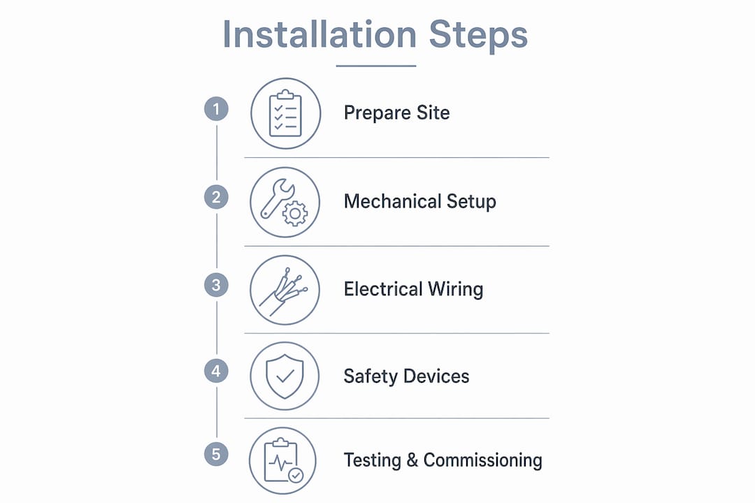
Motorized gate installation is the process of mechanically mounting a gate operator, running compliant electrical wiring, and commissioning safety devices to automate entry control at a property. Done correctly, the motorized gate installation steps produce a system that improves security, controls access, and reduces the need for manual intervention at driveways or facility entrances. This guide covers every phase: site prep, mechanical mounting, electrical wiring, and final commissioning. You will also find safety standards like UL 325, tools like laser levels, and wiring requirements under NEC Article 725 addressed directly.
What preparation and tools are needed before starting installation?
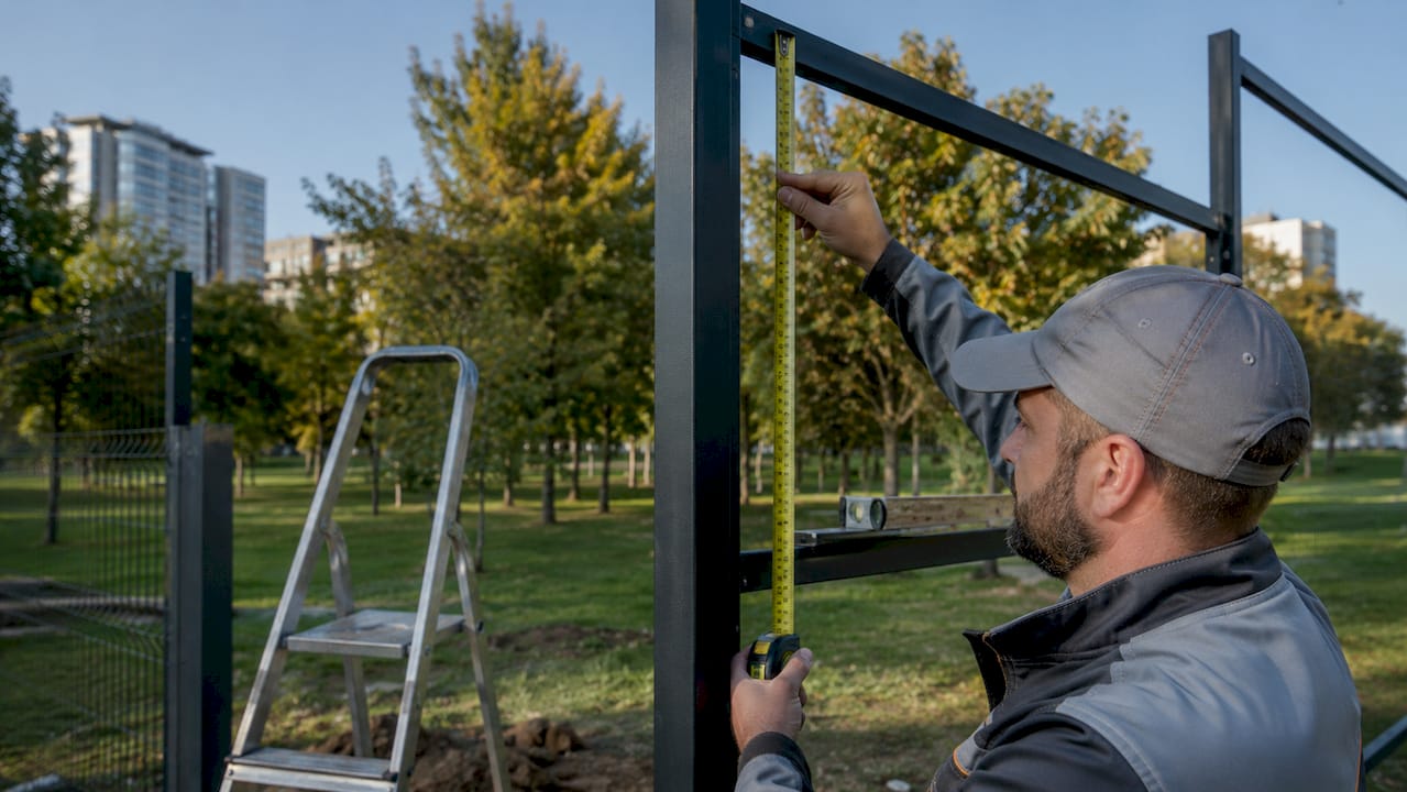
Preparation determines whether your automatic gate setup succeeds or stalls mid-project. Start with a thorough site assessment before ordering any equipment.
Measure everything. Record the gate opening width, the distance from the gate to the nearest power source, and the ground slope across the gate path. Uneven ground is the most common reason swing gate operators fail within the first year. Check soil stability where the motor post or pillar will be anchored. Soft or sandy soil requires deeper concrete footings, typically 24–36 inches, to prevent shifting under load.
Confirm permits early. Most jurisdictions require both an electrical permit for the 120V or 240V power feed and a structural permit for any new concrete work. Some municipalities also require a separate low-voltage permit. Skipping this step can result in a stop-work order or a failed inspection that forces you to redo wiring.
Assemble your tools and materials before breaking ground. You will need:
- Cordless drill and masonry bits
- Conduit bender and fish tape for running wire
- Laser level and plumb line for alignment
- Concrete mix and post-hole digger
- 12 AWG or 14 AWG wire for line voltage runs
- 18 AWG or 22 AWG wire for low-voltage accessories
- PVC or rigid metal conduit (separate runs for each voltage type)
- Gate operator kit with mounting hardware
Pro Tip: Buy 20% more conduit than your measurements suggest. Routing around obstacles always adds length, and running short mid-installation wastes hours.
Pour concrete footings for the operator base and gate posts at least 72 hours before mounting hardware. Rushing this step causes the base to shift under motor vibration, which throws off alignment within weeks.
How to mechanically install and align the motorized gate
Mechanical installation is where most DIY motorized gate projects go wrong. Millimetric precision in alignment using plumb lines and laser levels is required to avoid premature wear on the drive mechanism.
Follow this sequence for a swing or sliding gate operator:
- Set the gate on its hinges or track and confirm it swings or slides freely by hand. Testing gate movement manually before attaching the motor prevents force-setting errors and jerky operation later.
- Mount the operator base to the concrete footing using the anchor bolts supplied by the manufacturer. Do not substitute hardware.
- Attach the articulated arm or drive rack per the operator manual. For sliding gates, the rack must sit flush against the gate frame with no gaps. Even minor misalignments under load increase wear and cause premature failure.
- Check alignment with a laser level. The operator arm pivot point must align with the gate hinge axis on swing gates. On sliding gates, the drive pinion must sit centered on the rack at both the open and closed positions.
- Torque all fasteners to the manufacturer’s specified values. Under-torqued bolts vibrate loose; over-torqued bolts crack mounting plates.
- Move the gate by hand again with the arm attached. Resistance or binding means the arm geometry is off. Correct it before connecting power.
| Alignment Check | Tool Used | Pass Condition |
|---|---|---|
| Operator base level | Laser level | Zero deviation across base plate |
| Arm pivot to hinge axis | Plumb line | Arm and hinge share same vertical plane |
| Drive rack flush to gate | Straight edge | No gap greater than 1 mm along rack |
| Gate travel under load | Manual push test | Smooth movement with no binding |
Pro Tip: Mark the fully open and fully closed gate positions with chalk before programming electronic stops. Physical reference points make limit adjustments far faster.
What are the electrical wiring and safety device installation steps?
Electrical work is the phase where code compliance and personal safety overlap most directly. Get this wrong and you risk both failed inspections and genuine injury.
Separate your conduit runs from the start. Line-voltage and low-voltage wiring must run in separate conduits per NEC Article 725. Running a 120V power feed and a photocell wire in the same conduit creates interference and violates code. Use PVC conduit for underground runs and rigid metal conduit where the line is exposed above grade.
Key wiring steps for the gate installation process:
- Pull the line-voltage feed (120V or 240V) from a dedicated circuit breaker to the operator junction box. A 30 mA differential circuit breaker is recommended for the power supply circuit in many jurisdictions to protect against ground faults.
- Run a separate low-voltage conduit for photocells, edge sensors, keypads, and loop detectors.
- Connect photocell transmitter and receiver to the designated safety input terminals on the control board. Photocells span the gate hazard area and trigger the board to stop or reverse the gate when the beam is broken.
- Wire edge sensors and emergency stop buttons to their respective monitored inputs.
- Connect access control devices such as keypads or loop detectors to the access input terminals. Access input devices are wired and programmed for scheduling and controlled operation.
Safety device wiring comparison:
| Device | Voltage | Wiring Type | Control Board Input |
|---|---|---|---|
| Photocell sensor | 12V–24V DC | 18 AWG, low-voltage conduit | Safety/stop input |
| Edge sensor | 8.2 kΩ resistor loop | 22 AWG, low-voltage conduit | Monitored safety input |
| Emergency stop | Dry contact | 18 AWG, low-voltage conduit | E-stop input |
| Keypad | 12V–24V DC | 22 AWG, low-voltage conduit | Access input |
Safety device circuits on control boards must be properly wired and monitored. Incorrect termination prevents the operator from running or creates unsafe conditions where the gate moves without entrapment protection active. Always verify each safety input shows a healthy status on the control board display before closing the enclosure.
For additional guidance on safety sensor commissioning, the security system installation guide from Lowvoltagecorp covers device wiring and compliance testing in detail.
How to commission, test, and troubleshoot the motorized gate system
Commissioning is the phase that converts a mechanically and electrically complete installation into a working, safe system. Gate operator commissioning follows a fixed sequence: manual smoothness check, mechanical installation, stop and force programming, then sensor validation.
- Power on the operator and enter programming mode per the control board manual. Do not skip this step by guessing at default settings.
- Set travel limits using the electronic stop adjustment. Run the gate to the fully open position and set the open limit. Run it to fully closed and set the close limit. Use the chalk marks from the mechanical phase as your reference.
- Adjust force settings. Set the motor force low enough that the gate stops when you apply moderate hand pressure against it. This is the primary mechanical entrapment protection. UL 325 requires residential Class I operators to have at least two entrapment protection devices active.
- Test photocell function. Close the gate and break the photocell beam mid-travel with your hand or a cardboard tube. The gate must stop and reverse immediately. If it does not, recheck the wiring at the safety input terminal.
- Test edge sensor function. Apply pressure to the edge sensor during a closing cycle. The gate must stop within one inch of contact.
- Test the access control devices. Enter a valid code on the keypad and confirm the gate opens. Test a loop detector by driving a vehicle over it.
- Run five full open and close cycles without interruption and observe for hesitation, grinding, or limit overshoot.
Pro Tip: Document every programmed setting, including force values and limit positions, in a physical log stored at the operator enclosure. When a technician troubleshoots the system two years from now, that log saves hours.
Common issues after commissioning include gate hesitation at the start of travel (usually a force setting too low), photocell faults (misaligned sensors or dirty lenses), and limit overshoot (mechanical stops set too loosely). For a full breakdown of post-installation issues, the motorized gate troubleshooting guide from Lowvoltagecorp covers the most frequent failure points property managers encounter.
Schedule a maintenance check every six months. Lubricate the drive rack and pivot points, inspect conduit seals for moisture intrusion, and clean photocell lenses. Consistent maintenance is the single biggest factor in operator lifespan.
Key takeaways
Successful motorized gate installation requires precise mechanical alignment, code-compliant electrical wiring, and validated safety device commissioning before the system is considered operational.
| Point | Details |
|---|---|
| Prepare the site first | Assess ground level, confirm permits, and cure concrete footings before mounting any hardware. |
| Alignment determines longevity | Use a laser level and plumb line to align the operator arm or drive rack to prevent premature wear. |
| Separate conduit runs are required | Run line-voltage and low-voltage wiring in separate conduits per NEC Article 725. |
| Safety devices must be monitored | Wire photocells and edge sensors to monitored control board inputs and verify each shows a healthy status. |
| Commission in sequence | Set limits and force before testing sensors, and document all programmed values for future maintenance. |
What i’ve learned installing motorized gates that most guides skip
Most installation guides treat the gate and the operator as two separate problems. They are not. The gate itself is the foundation. If it does not move freely by hand before you attach a motor, no amount of force adjustment will fix the underlying problem. I have seen operators burn out within 90 days because the installer skipped the manual movement test and compensated with maximum force settings instead.
Alignment is the other issue that gets underestimated. A quarter-inch of misalignment between the operator arm pivot and the gate hinge axis on a swing gate creates a binding force that compounds with every cycle. Over 10,000 cycles, that adds up to real mechanical damage. A laser level costs less than one service call.
The safety device wiring step is where I see the most shortcuts taken, and it is the most dangerous place to cut corners. UL 325 compliance is not just a checkbox for inspectors. It is the standard that determines whether your gate stops before it injures someone. Photocell re-opening logic during closing requires precise alignment and correct wiring to function reliably. A sensor that is wired but not monitored by the control board gives you false confidence. Always confirm the board registers each safety input as active before you call the job done.
My advice for anyone working with inspectors: bring the operator manual and a printed wiring diagram to the inspection. Inspectors who are unfamiliar with gate automation often focus on what they can see. A clear diagram shows them the monitored safety circuit logic and typically shortens the inspection. Document everything, including the force test results and sensor response times. That record protects you if a liability question comes up later.
— Aaron
How Lowvoltagecorp supports your gate installation project
Lowvoltagecorp specializes in motorized gate installation, repair, and maintenance for property owners and managers across South Florida. Whether you are completing a DIY install and need a professional commissioning check, or you want a full turnkey installation, Lowvoltagecorp’s team handles the mechanical, electrical, and safety device work to code.

Property managers looking to reduce long-term costs will find practical options in Lowvoltagecorp’s security upgrade guide for South Florida, which covers motorized gate systems alongside cameras and network infrastructure. For ongoing care after installation, the security equipment maintenance guide gives you a clear schedule to protect your investment.
FAQ
What does UL 325 require for residential gate operators?
UL 325 requires residential Class I gate operators to have at least two active entrapment protection devices. These typically include a force-limiting function and a photocell or edge sensor.
Do i need a permit to install an electric gate?
Most jurisdictions require an electrical permit for the power feed and a structural permit for concrete work. Check with your local building department before starting any automatic gate setup.
Can i run photocell wiring in the same conduit as the power feed?
No. NEC Article 725 requires low-voltage accessory wiring and line-voltage power wiring to run in separate conduits to prevent interference and maintain code compliance.
How do i know if my gate operator is properly aligned?
Move the gate by hand with the operator arm attached. Any resistance or binding indicates a geometry problem. Use a laser level to confirm the arm pivot aligns with the gate hinge axis before running powered cycles.
How often should a motorized gate system be serviced?
A maintenance check every six months covers lubrication of the drive rack, inspection of conduit seals, and cleaning of photocell lenses. Consistent service is the primary factor in extending operator lifespan.