Power ratings describe the maximum electrical power a device can safely handle or deliver, measured in watts (W) and volt-amperes (VA). For property and facility managers, understanding power ratings is not optional. It determines whether your UPS units, transformers, and motors survive their workloads or fail at the worst possible moment. This guide breaks down the core concepts behind power ratings explained in practical terms: what watts and VA actually mean, how to read a nameplate, and how to apply that knowledge to equipment sizing, installation, and preventive maintenance.
What are watts, VA, and power factor in power ratings?
Watts measure real power, the portion of electrical energy that actually performs work. Running a motor, powering a server, or charging a battery all consume watts. VA, or volt-amperes, measures apparent power, which is the total electrical load a circuit carries including reactive components that do not perform useful work. The gap between the two is not a rounding error. It is a fundamental property of AC electrical systems that directly affects how you size equipment.
Real power in watts and apparent power in VA are both required metrics for sizing UPS systems correctly. Treating them as interchangeable is one of the most expensive mistakes a facility manager can make. A UPS that cannot deliver enough VA will enter overload protection even when its watt rating appears sufficient.
Power factor (PF) is the ratio of watts to VA, expressed as a number between 0 and 1. A 1000VA UPS rated at 700W carries a power factor of 0.7, meaning only 70% of its apparent power capacity translates into usable real power. The lower the power factor, the more VA you need to deliver the same amount of working watts.

Pro Tip: When comparing UPS models from CyberPower, APC, or Eaton, always check both the VA and watt ratings on the spec sheet. A unit with a high VA but low PF delivers less usable power than its headline number suggests.
The table below shows how power factor varies across common facility equipment and what that means for sizing:
| Equipment type | Typical power factor | Sizing implication |
|---|---|---|
| Modern servers | 0.90 to 0.95 | VA and watt ratings are close; less oversizing needed |
| Older office equipment | 0.65 to 0.70 | Significant VA overhead required beyond watt load |
| AC motors | 0.70 to 0.85 | Reactive load is substantial; size UPS and transformers accordingly |
| LED lighting systems | 0.85 to 0.95 | Generally efficient; verify driver PF on spec sheets |
Equipment power factors vary widely across categories, and using an average estimate instead of actual values leads to chronic undersizing or unnecessary capital spend on oversized equipment.
How power ratings affect transformer and motor selection
Transformers are rated in kVA, not kW, and the reason is thermal. A transformer’s temperature rise depends on total current flowing through its windings, which includes both real and reactive components. Transformer thermal limits depend on total current, not just real power demand, which is why kVA is the correct unit for specifying transformer capacity. Selecting a transformer based on kW alone ignores the reactive load and risks overheating the unit under normal operating conditions.
Reading a transformer nameplate correctly requires attention to four values: kVA rating, primary and secondary voltage, impedance percentage, and tap range. The impedance value tells you how much voltage drop to expect under full load and how fault current will behave during a short circuit. Tap ranges allow minor voltage adjustments to compensate for supply variations at the facility level.
For motors, the nameplate tells a different story. Key values include:
- Full Load Amps (FLA): The current draw at rated load and voltage, used directly for conductor and breaker sizing
- kW or horsepower rating: The real power output at the shaft, not the electrical input
- Voltage and frequency: Must match the supply circuit exactly
- Service factor: A multiplier indicating how much overload the motor can sustain for short periods
- Insulation class: Defines the maximum operating temperature the motor windings can tolerate
NEC Article 430 governs motor circuit design, requiring conductors sized at 125% of FLA and overload relays set to the nameplate FLA for correct trip coordination. Skipping this step and sizing conductors to the actual measured current instead of the NEC table values is a code violation that also leaves motors unprotected during starting transients.
A practical example: a 15 HP, 460V, three-phase motor with a nameplate FLA of 21 amps requires conductors rated for at least 26.25 amps (21 x 1.25) and an overload relay set to 21 amps. The breaker size follows NEC 430 tables based on motor type, not just the FLA.
Pro Tip: Apply a 20 to 25% safety margin when sizing transformer kVA for new installations. Transformer kVA safety margins of this size account for load growth, inrush currents, and future equipment additions without requiring a costly transformer swap.
What are common pitfalls when interpreting power ratings?
The most frequent error facility managers make is treating VA as equivalent to watts when planning UPS capacity. A 1500VA UPS can shut down when the connected load exceeds its 900W watt rating, even if the VA headroom appears adequate. The inverter’s real power limit is the actual operating constraint, not the VA figure on the front panel.
UPS runtime planning compounds this problem. Runtime calculations use actual load watts, not the VA rating of the UPS. A 3000VA unit with a 0.9 power factor delivers a maximum of 2700W, but if your connected load draws 1500W, runtime is calculated against 1500W, not 3000VA. Facility managers who plan battery backup based on VA figures consistently overestimate how long their systems will run during an outage.
A second common pitfall is relying on nameplate maximum ratings without accounting for inrush currents. Motors, compressors, and HVAC units draw three to seven times their FLA during startup. A system that operates within nameplate limits under steady-state conditions can still trip breakers or overload a UPS during a startup sequence if inrush was not factored into the design.
The table below compares typical equipment power factors and their UPS sizing implications:
| Equipment | Power factor | UPS sizing note |
|---|---|---|
| Server rack (modern) | 0.95 | Size UPS watts close to load watts |
| Mixed office load | 0.70 | Add 30% VA overhead above watt load |
| HVAC control panel | 0.75 | Account for motor inrush at startup |
| Security camera NVR | 0.85 | Moderate overhead; verify with actual measurement |
Pro Tip: Measure real power with a power analyzer over a full operating cycle, not just at a single point in time. Measurement variance within ±10% is acceptable and captures startup currents and transient events that nameplate data alone will miss.
How to apply power ratings knowledge to installation and maintenance
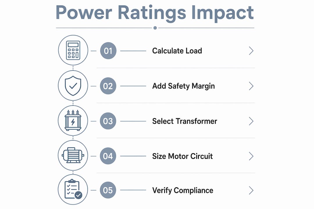
Translating power ratings knowledge into daily facility operations requires a structured approach. The following steps give you a repeatable process for equipment sizing, installation, and ongoing maintenance.
- Size UPS units using both watts and VA. Start with the total watt load of connected equipment, add a 20 to 25% safety margin, then verify the required VA by dividing the target watts by the lowest power factor in your load mix. Cross-check both figures against the UPS spec sheet before purchasing.
- Read transformer nameplates before specifying replacements. Match kVA, primary voltage, secondary voltage, and impedance to the existing circuit. A transformer with the correct kVA but wrong impedance will cause protection coordination problems downstream.
- Incorporate power ratings into preventive maintenance schedules. Load testing under controlled conditions once or twice per year confirms that protection devices trip at the correct thresholds and that equipment has not drifted from its nameplate specifications.
- Monitor real-time power factor at the panel level. Power factor degradation over time signals aging capacitors, failing motor windings, or load mix changes that require attention before they cause failures.
- Verify compliance with NEC guidelines during every installation. NEC 430 for motors and NEC 700 for emergency systems provide the minimum sizing requirements that also serve as your liability baseline.
- Use power ratings data when planning for UPS protection in security and low-voltage systems. Undersized UPS units in camera and access control circuits are a leading cause of unplanned downtime in commercial properties.
Verifying nameplate ratings with actual load measurements and confirming that protective devices coordinate with real current waveforms is the maintenance best practice that separates reactive facilities from proactive ones. It prevents nuisance trips, extends equipment life, and gives you documented evidence of system health for insurance and compliance purposes.
For energy-efficient property management, power factor correction at the panel level can reduce apparent power demand and lower utility costs, particularly in facilities with heavy motor loads.
Key takeaways
Correct power rating interpretation requires matching both watts and VA to actual load conditions, not just nameplate maximums.
| Point | Details |
|---|---|
| Watts vs. VA distinction | Always size UPS and transformers using both metrics; treating them as equal causes overloads and shutdowns. |
| Power factor impact | A lower power factor means less usable watts per VA; verify PF for every equipment category in your load mix. |
| Transformer sizing in kVA | Transformers are rated in kVA due to thermal limits; apply a 20 to 25% safety margin for all new installations. |
| NEC 430 motor compliance | Size conductors at 125% of nameplate FLA and set overload relays to FLA for correct protection coordination. |
| Measure, don’t assume | Use a power analyzer over a full operating cycle to capture inrush currents and transient loads that nameplates do not show. |
Why power rating literacy pays for itself
Most facility managers I work with come in confident about watts and completely blindsided by VA. The first time a brand-new UPS shuts down a server room during a storm, and the cause turns out to be a watt limit nobody checked, that lesson costs real money. I have seen it happen in buildings with otherwise excellent electrical infrastructure.
The uncomfortable truth is that nameplate data is a starting point, not a guarantee. Manufacturers rate equipment under ideal conditions. Your facility is not ideal. It has aging wiring, mixed load types, motors that have been rewound twice, and transformers that were sized for a tenant who moved out three years ago. Relying on nameplates without measuring actual loads is the electrical equivalent of navigating by a map that was drawn before the roads were built.
What I advocate for is a simple shift in practice: treat power ratings as hypotheses to be confirmed, not facts to be accepted. Measure your loads. Document your power factors. Build your safety margins into the design from day one. Facilities that do this spend less on emergency repairs, pass inspections without surprises, and extend the service life of expensive equipment by years.
If your systems are complex enough to involve large transformer banks or multi-motor circuits, bring in a licensed electrical engineer for the sizing calculations. The cost of that consultation is a fraction of the cost of a transformer failure or a code violation discovered during a sale or refinancing.
— Aaron
How Lowvoltagecorp supports your facility’s power systems
Lowvoltagecorp works directly with property and facility managers across South Florida to install, maintain, and troubleshoot low-voltage electrical systems where power rating errors cause the most damage. From UPS sizing for security camera networks to transformer selection for motorized gate systems, the team at Lowvoltagecorp brings field-tested knowledge to every project.

If your facility relies on wired network infrastructure, proper power planning is the foundation that keeps everything running. Lowvoltagecorp’s approach to wired network solutions for South Florida property managers includes power capacity planning as part of every installation, so your systems are sized correctly from the start and built to last.
FAQ
What is the difference between watts and VA in power ratings?
Watts measure real power that performs actual work, while VA measures apparent power including reactive load. The ratio between them is the power factor, which determines how much of a device’s VA rating translates into usable watts.
Why are transformers rated in kVA instead of kW?
Transformer ratings use kVA because thermal limits depend on total current, including reactive components, not just real power. A transformer sized only in kW would be undersized for loads with low power factors and risk overheating.
How do I size a UPS correctly using power ratings?
Calculate the total watt load of connected equipment, add a 20 to 25% safety margin, then divide by the lowest power factor in your load mix to determine the required VA. Verify both the watt and VA ratings on the UPS spec sheet before purchasing.
What does NEC 430 require for motor circuit sizing?
NEC Article 430 requires conductors sized at 125% of the motor’s nameplate full load amps (FLA) and overload relays set to the nameplate FLA for correct trip coordination and code compliance.
Why should I measure actual loads instead of relying on nameplates?
Nameplate ratings reflect maximum values under ideal conditions. Actual facility loads include inrush currents, transient events, and load mix variations that nameplates do not capture. Measuring with a power analyzer over a full operating cycle gives you the accurate data needed for reliable system design.