What is PoE technology?
Power over Ethernet, or PoE, does exactly what the name says: it carries both electrical power and data over a single Ethernet cable. Instead of running a separate power line to every networked device, you plug in one cable and get both connectivity and electricity at the same time. The IEEE 802.3 standard governs three main tiers: 802.3af delivers up to 15.4W, 802.3at pushes that to 30W, and 802.3bt reaches 90W, all over Cat5e, Cat6, or Cat6a cabling with a maximum run of 100 meters.
Two components make the whole system work. The Power Sourcing Equipment (PSE) is the device that supplies power, typically a PoE switch or a standalone injector. The Powered Device (PD) is whatever receives that power: a camera, a phone, an access point. No separate wall outlet, no extra power adapter, no electrician required for the power side.
Key facts at a glance:
- Single cable carries both data and DC electrical power
- Compatible cable types: Cat5e, Cat6, Cat6a
- IEEE standards: 802.3af (15.4W), 802.3at (30W), 802.3bt (90W)
- Maximum cable distance: 100 meters per segment
- Core components: Power Sourcing Equipment (PSE) and Powered Device (PD)
- Eliminates separate power supplies and dedicated electrical outlets
How does PoE work? The handshake explained
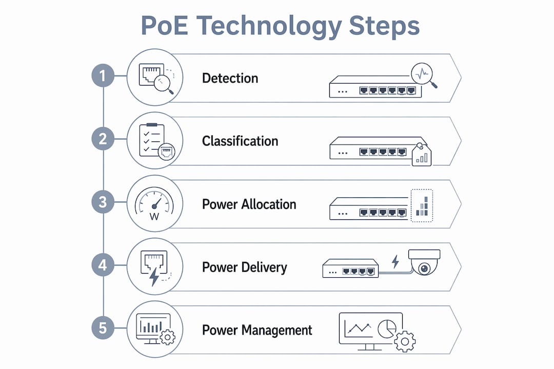
Before a PoE switch sends a single watt to a connected device, it runs a safety check. The PSE detects a 25-kilohm resistor signature from the PD, confirming the device is actually PoE-compatible. If that signature is missing or out of range, the switch withholds power entirely, protecting whatever is plugged in from getting fried.

After detection comes classification. The PD signals how much power it needs, and the PSE allocates accordingly. Only then does power flow. This four-step sequence, detection, classification, power-up, and ongoing monitoring, runs automatically every time a device connects.
The process in order:
- Detection: PSE applies a low test voltage and checks for the 25kΩ resistor signature
- Classification: PD signals its power class (0–8 under 802.3bt), telling the PSE its maximum draw
- Power-up: PSE ramps voltage to the operating level and begins supplying power
- Monitoring: PSE continuously checks for disconnection or overload and cuts power if needed
Two negotiation protocols, LLDP (Link Layer Discovery Protocol) and CDP (Cisco Discovery Protocol), allow the PSE and PD to communicate power requirements dynamically after startup. This lets devices request more or less power as conditions change, which is especially useful for PTZ cameras that draw more current when actively moving.
Pro Tip: Not all PoE injectors perform this handshake. Standard IEEE-compliant injectors negotiate with the device before supplying power. Passive injectors push constant voltage regardless of what is plugged in, which can permanently destroy non-PoE equipment. Always check for IEEE 802.3 compliance before buying an injector.
IEEE PoE standards: how the technology evolved
PoE did not arrive fully formed. The first formal standard, IEEE 802.3af, came out in 2003 and covered basic devices like VoIP phones and early IP cameras at up to 15.4W per port. Six years later, 802.3at (often called PoE+) doubled the available power to 30W, opening the door to more demanding devices like dual-radio wireless access points.
The real leap came with 802.3bt in 2018. Also called PoE++ or 4PPoE, it uses all four twisted pairs in the cable instead of two, reaching 60W at Type 3 and 90W at Type 4. That is enough to power pan-tilt-zoom cameras, high-performance access points, and even thin-client computers. Cisco introduced its proprietary UPOE standard before 802.3bt was finalized, delivering 60W over a single cable, which showed the market where things were heading.
Standards timeline:
- 802.3af (2003): Up to 15.4W at the PSE, 12.95W at the PD; uses two cable pairs; supports Class 0–3 devices
- 802.3at / PoE+ (2009): Up to 30W at the PSE, 25.5W at the PD; backward compatible with 802.3af; supports Class 4
- 802.3bt / PoE++ (2018): Type 3 delivers 60W, Type 4 delivers 90W; uses all four pairs; supports Class 5–8; backward compatible with earlier standards
Physical and compatibility details:
- All three standards work over Cat5e or better at up to 100 meters
- 802.3bt supports data rates up to 10GBASE-T
- Backward compatibility means a newer PSE can power older PDs, but the PD will only draw what it is rated for
- Mixing device power classes with an undersized switch is the most common cause of port instability
Always match the power class of your devices to the switch’s per-port and total power budget. A switch rated at 30W per port cannot safely run a 60W PTZ camera, regardless of how many ports are open.
Why PoE saves money and simplifies your network
The most direct cost benefit is the elimination of separate electrical circuits. Every IP camera or access point that runs on PoE is one fewer outlet you need an electrician to install. PoE switches use low-voltage DC power, which means the cabling work falls under low-voltage rules in most US jurisdictions, not the licensed-electrician requirements that apply to standard AC wiring.

Centralized power management is the second major advantage. When all your devices draw power from a single PoE switch, you can put that switch on a UPS (uninterruptible power supply) and keep cameras, phones, and access points running through a power outage. You also get the ability to remotely power-cycle a frozen device from a management console, no ladder or site visit required.
Benefits worth knowing:
- Cost savings: Fewer electrical outlets, less conduit, lower installation labor
- Placement flexibility: Devices go wherever the Ethernet cable reaches, not wherever an outlet exists
- Safety: Low-voltage DC is far less hazardous than AC wiring; the handshake prevents accidental overpowering
- Centralized UPS backup: One UPS on the switch protects every connected device
- Remote management: Power cycling and reset from a management interface, critical for hard-to-reach installations
- Scalability: Adding a device means running one cable, not two
For property managers and IT teams handling multi-site deployments, the ability to reboot a camera or access point remotely is not a convenience. It is hours of saved travel time per year.
What devices actually run on PoE?
The short answer is: most of the networked devices you would install in a commercial or residential building. IP cameras, wireless access points, VoIP phones, LED lighting, sensors, and building automation systems all have PoE-compatible versions. If you are setting up a security camera installation, PoE is almost certainly the right power method.
Higher-power 802.3bt devices have expanded what is possible. PTZ cameras that pan, tilt, and zoom draw more current than fixed cameras, and 802.3bt handles them without a separate power supply. Smart building applications, including HVAC sensors, door access controllers, and digital signage, increasingly rely on PoE because it simplifies both installation and ongoing management. For IoT device setups in modern buildings, PoE is often the backbone that makes everything practical.
Common PoE device categories:
- IP cameras (fixed and PTZ): The most common PoE application; 802.3af covers basic cameras, 802.3bt handles PTZ
- Wireless access points: Dual-radio and tri-radio APs often need 802.3at or 802.3bt
- VoIP phones: Typically Class 2 or 3 devices, well within 802.3af limits
- LED lighting: PoE lighting systems allow per-fixture dimming and scheduling over the data network
- Sensors and IoT devices: Temperature, occupancy, and environmental sensors with minimal power draw
- Door access controllers: Card readers and electronic locks that benefit from centralized power management
- Building automation: HVAC controls, digital signage, and intercom systems increasingly use PoE
Infrastructure accessories:
- PoE injector: Adds PoE capability to a single port on a non-PoE switch
- PoE splitter: Separates power and data at the device end, useful for non-PoE devices that need a separate power input
- PoE extender: Extends the 100-meter cable limit by repeating both power and data
For network wiring in multi-unit properties, PoE dramatically reduces the number of cable runs and junction boxes needed compared to traditional separate-power installations.
PoE terminology you need to know
Getting the vocabulary right prevents expensive mistakes when specifying equipment. Here are the terms that come up constantly in PoE deployments:
- PSE (Power Sourcing Equipment): The device that supplies power over the Ethernet cable. Usually a PoE switch (endpoint PSE) or a PoE injector (midspan PSE).
- PD (Powered Device): Any device that receives power from the PSE. Cameras, phones, access points, and sensors are all PDs.
- PoE switch: A network switch with built-in PSE circuitry on some or all ports. The most common way to deploy PoE at scale.
- PoE injector: A standalone device that adds PoE to a single cable run from a non-PoE switch. Useful for adding one device without replacing the switch.
- PoE splitter: Sits at the PD end and splits the combined power-and-data signal into separate outputs, allowing non-PoE devices to use PoE infrastructure.
- Power budget: The total wattage a PoE switch can distribute across all active ports simultaneously. Not the same as port count times per-port maximum.
- Signature detection: The PSE’s check for the 25kΩ resistor in the PD before supplying power.
- Power classification: The PD’s signal to the PSE indicating which power class (and therefore how many watts) it needs.
- LLDP (Link Layer Discovery Protocol): A standard protocol that lets PSEs and PDs negotiate power levels dynamically after the initial handshake.
- CDP (Cisco Discovery Protocol): Cisco’s proprietary equivalent to LLDP for power negotiation on Cisco equipment.
- PoE+ (802.3at): The 30W standard, the most widely deployed tier in enterprise networks.
- PoE++ (802.3bt): The 60W/90W standard using all four cable pairs, suited for high-power devices.
- UPOE: Cisco’s proprietary 60W standard, predating 802.3bt, still found in older Cisco infrastructure.
Understanding the difference between a switch’s per-port maximum and its total power budget is the single most useful piece of vocabulary here. A 24-port switch rated at 30W per port does not necessarily have 720W of total budget. Check the spec sheet for the aggregate figure before you design the deployment.
Best practices and safety for PoE deployments
The most common mistake in PoE deployments is using a passive PoE injector without checking device compatibility first. Passive injectors supply constant voltage with no handshake, no signature detection, and no power classification. Plug a non-PoE device into one and you may destroy it instantly. IEEE 802.3-compliant equipment performs the full detection and classification sequence every time, which is the only reliable protection against this kind of damage.
Power budgeting is where most larger deployments run into trouble. Proper PoE power budgeting requires adding up the worst-case power draw of every connected device and comparing that total against the switch’s aggregate budget, not its per-port rating. A switch that runs out of power budget does not shut down cleanly. It drops ports intermittently, which looks like a network problem until you trace it back to the power side.
Deployment best practices:
- Use only IEEE 802.3-compliant switches and injectors; verify compliance on the spec sheet, not just the marketing copy
- Calculate aggregate device power needs before purchasing a switch; leave at least 20% headroom in the budget
- Run Cat5e at minimum; Cat6 or Cat6a is worth the small cost difference for any 802.3bt deployment
- Keep cable runs under 100 meters; beyond that, use a PoE extender rather than a longer cable
- Place the PoE switch on a UPS to maintain power to cameras and access points during outages
- Use LLDP-capable switches for dynamic power negotiation, especially in mixed-device environments
- Label every cable run with the device type and power class at both ends
Pro Tip: Periodically verify that connected devices still present the correct signature and power class, especially after firmware updates. A device that reports a different power class after an update can throw off your power budget calculations and cause intermittent drops on neighboring ports.
Remote management capability is worth building in from the start. Remote power cycling from a managed switch interface lets you reboot a frozen camera or access point without a site visit, which pays for the cost of a managed switch many times over in a multi-site deployment. For network installation best practices that cover both PoE and broader structured cabling, the planning principles are the same: document everything, budget conservatively, and use compliant hardware throughout.
Key Takeaways
PoE technology delivers both data and DC electrical power over a single Ethernet cable, governed by IEEE standards that range from 15.4W to 90W, eliminating separate power supplies and enabling centralized management of networked devices.
| Point | Details |
|---|---|
| IEEE standards define power tiers | 802.3af delivers 15.4W, 802.3at delivers 30W, and 802.3bt delivers up to 90W per port. |
| Safety handshake prevents damage | The PSE detects a 25kΩ resistor signature before supplying power, protecting non-PoE devices. |
| Power budget is the critical number | Sum worst-case device draws and compare against the switch’s aggregate budget, not its port count. |
| Passive injectors carry real risk | Unlike IEEE-compliant equipment, passive injectors supply constant voltage with no device detection. |
| One cable replaces two | PoE eliminates separate electrical runs, reducing installation cost and enabling flexible device placement. |
Lowvoltagecorp installs and maintains PoE-powered security camera systems, wired and wireless networks, and low-voltage infrastructure across South Florida. If you are planning a camera deployment or need help sizing a PoE switch for an existing network, the security camera wiring guide covers the full installation process from cable selection to final testing.